
Description
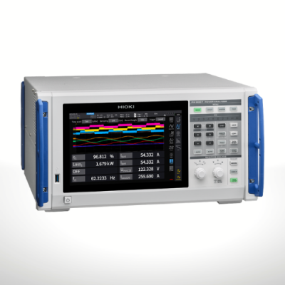
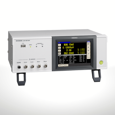
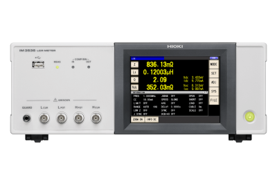
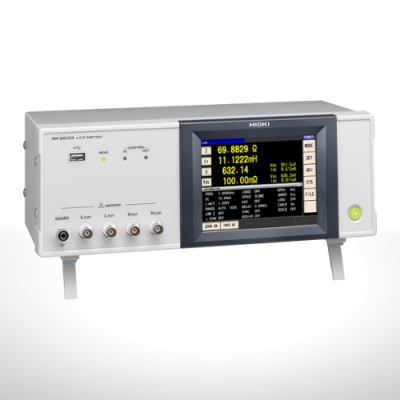
Hioki LCR Meters and Impedance Analyzers range from 1mHz to 3GHz devices to suit a wide range of applications in the testing of electronic components.
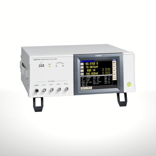
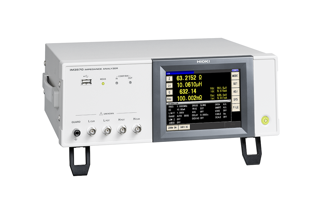
The IM3570 is ideal for use in applications requiring low-ESR measurement on the order of several milliohms, for example testing of functional polymer capacitors, due to its superior low-impedance repeatability.
Impedance Analyzer IM3570: Measuring the resonance characteristics of a piezoelectric element
The IM3570, which serves as both an LCR meter and an impedance analyzer, can generate pass/fail judgments on the resonance condition using its frequency sweep measurement and peak comparator functions, and also conduct continuous inspections under different conditions including pass/fail decisions via 1 kHz and 120 Hz LCR testing.
In this way, it is possible to make both frequency sweep measurement and LCR measurement with a single instrument.
Probes and Test Fixtures (15)
When using the 9268-10 or 9269-10, external constant-voltage and constant-current sources are required.
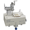
SMD TEST FIXTURE IM9100
Learn more
• Direct-connection testing
• Test SMDs with electrodes on the bottom
• DC to 8MHz
• Measurable sample sizes: 01005 to 0402 (EIA)
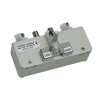
Direct connection type, For measuring SMDs with electrodes on the bottom; DC to 120 MHz, test sample dimensions: 1.0 mm (0.04 in) to 4.0 mm (0.16 in) wide, max. 1.5 mm (0.06 in) high
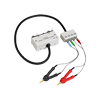
Cable length 1 m (3.28 ft), DC to 8 MHz, impedance characteristics of 50 Ω, 4-terminal pair configuration, measurable conductor diameter: ø0.3 (0.01 in) to 5 mm (0.20 in)
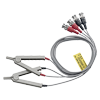
Cable length 1 m (3.28 ft), DC to 200 kHz, impedance characteristics of 50 Ω, 4-terminal pair configuration, measurable conductor diameter: ø0.3 (0.01 in) to 5 mm (0.20 in)
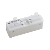
Direct connection type, For measuring SMDs with electrodes on the side; DC to 120 MHz, test sample dimensions: 3.5 mm ±0.5 mm (0.14 in ±0.02 in)
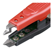
To replace the tip on the L2001, small size
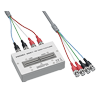
Cable length 1 m (3.28 ft), DC to 8 MHz, impedance characteristics of 50 Ω, 4-terminal pair configuration, measurable conductor diameter: ø0.3 (0.01 in) to 1.5 mm (0.06 in)
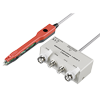
PINCHER PROBE L2001
Learn more
• DC to 8MHz, 50Ω termination
• Tip electrode spacing: 0.3 to 6 mm
• Measurable sample size: 0603 (EIA)
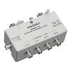
Direct connection type, 40 Hz to 2 MHz, maximum applied current of DC 2 A
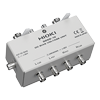
Direct connection type, 40 Hz to 8 MHz, maximum applied voltage of DC ±40 V
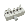
Direct connection type, DC to 8 MHz, measurable conductor diameter: ø0.3 (0.01 in) to 2 mm (0.08 in)
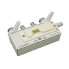
Direct connection type, DC to 8 MHz, Test sample dimensions:1 mm (0.04 in) to 10 mm (0.39 in)
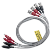
Cable length 1 m (3.28 ft), DC to 200 kHz, impedance characteristics of 50 Ω, measurable conductor diameter: φ0.3 mm (0.01 in) to 2 mm (0.08 in)
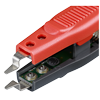
To replace the tip on the L2001, regular size, bundled with the L2001
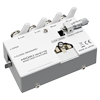
SMD TEST FIXTURE IM9110
Learn more
• For direct connection two-wire testing
• DC to 1 MHz
• Measurable sample size: 008004 (EIA)
PC Communication (2)
2 m (6.56 ft) length
*This product is not supplied with measurement probes or test fixtures.
Please select and purchase the measurement probe or test fixture options appropriate for your application separately.
Basic Specifications
| Measurement modes | LCR mode, Analyzer mode (Sweeps with measurement frequency and measurement level), Continuous measurement mode | |||||
|---|---|---|---|---|---|---|
| Measurement parameters | Z, Y, θ, Rs (ESR), Rp, Rdc (DC resistance), X, G, B, Cs, Cp, Ls, Lp, D (tanδ), Q |
|||||
| Measurement range | 100 mΩ to 100 MΩ, 12 ranges (All parameters are determined according to Z) | |||||
| Display range | Z, Y, Rs, Rp, Rdc, X, G, B, Ls, Lp, Cs, Cp : ±(0.000000 [unit] to 9.999999G [unit], Absolute value display for Z and Y only θ : ±(0.000° to 180.000°), D : ±(0.000000 to 9.999999) Q : ±(0.00 to 99999.99), Δ % : ±(0.0000% to 999.9999%) |
|||||
| Basic accuracy | Z ±0.08% rdg. θ: ±0.05° | |||||
| Measurement frequency | 4 Hz to 5 MHz (5 digits setting resolution, minimum resolution 10 mHz) | |||||
| Measurement signal level | Normal mode: V mode/CV mode: 5 mV to 5 Vrms (up to 1 MHz) 10 mV to 1 Vrms (1.0001 MHz to 5 MHz), 1 mVrms steps CC mode: 10 μA to 50 mArms (up to 1 MHz) 10 μA to 10 mArms (1.0001 MHz to 5 MHz), 10 μArms steps Low impedance high accuracy mode: V mode/CV mode: 5 mV to 1 Vrms (up to 100 kHz), 1 mVrms steps CC mode:10 μA to 100 mArms (100 mΩ and 1Ω ranges of up to 100 kHz), 10 μArms steps |
|||||
| Output impedance | Normal mode: 100 Ω, Low impedance high accuracy mode: 10 Ω | |||||
| Display | 5.7-inch color TFT, display can be set to ON/OFF | |||||
| Measurement time | 0.5 ms (100 kHz, FAST, display OFF, representative value) | |||||
| Functions | DC bias measurement, Comparator, BIN measurement (classification), Panel loading/saving, Memory function | |||||
| Interfaces | EXT I/O (handler), RS-232C, GP-IB, USB communication, USB memory, LAN | |||||
| Power supply | 90 to 264 V AC, 50/60 Hz, 150 VA max. | |||||
| Dimensions and mass | 330 mm (12.99 in) W × 119 mm (4.69 in) H × 307 mm (12.09 in) D, 5.8 kg (204.6 oz) | |||||
| Included accessories | Power cord × 1, Instruction manual × 1, PC communication instruction manual (CD-R) × 1 | |||||